
Copyright 2011. figNoggle Designs.
7x10, 7x12, 7x14 Mini-Lathe Information
Website Links
Post a link to your website or view other hobby and machine and metalworking websites for free.
|
Rent Mill & Lathe DVDs at Smartflix | Great aluminum & steel prices at OnlineMetals Round Column Mill Drill Spindle Quill Removal Procedure
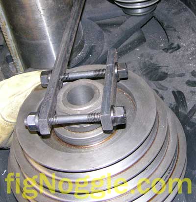
If you've read some of our previous posts about this mill's vibration problem and our attempts to get things working properly, you'll know that we're trying just about everything to get this mill to produce quality surface finishes. The reality is that the motor is what's causing the vibration and the vibration is traveling across the entire head to the column to the table. We've run some tests of vibration, but we'll get to that later. On a whim one day, we grabbed the spindle and pushed and pulled it in the two axes. We had one had on the spindle and one hand loosely placed at the top of the spindle spline. There was a bit of play. This bit of play led us to believe that it this looseness could have also contributed to the surface finish problem. As it turns out, the spindle appeared to be OK and that it was most likely the quill (spindle cartridge) and head casing that had some play. Yes, we even had the quill lock lever cranked down during some of the initial tests and yet somehow, there was still play. Strange indeed. We needed a way to eliminate as many variables from this equation as possible, and since the mill was old and the grease that was visible was oxidizing and in some cases crusted, it was time to take the spindle out and regrease them. Here's how to do this: First thing's first. If you want to remove the spindle, you DO NOT need to take the pulley off. But if you wanted to here's how. (Then we'll get back to the spindle/quill removal procedure). Turn off the machine! Remove the top belt cover. Then, you'll need to remove the left-hand threaded lock nut. You can use a large crescent wrench or pipe wrench, but we opted to make a quick and dirty lever out of some old steel bar. We drilled two holes both on the short piece and long piece, threaded the 3/8" step block clamp down set studs through them (they have many uses!) and tightened it down across the nut. Then we wedged the long bar against the column and using gloves, grabbed the pulley and rotated it until the nut came loose.
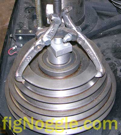
The designers of this machine never included a spindle lock. Sadly, this one little feature could have made this and tool changes much easier.. Next up is to remove the pulley. We were half way onto making our own gear puller (to grab the largest pulley) when we thought of trying one we had on hand. You can use a 4" puller, but the jaws will need to be loose in order to fit over the smallest pulley. Crank the center bolt and the pulley "pops" off.
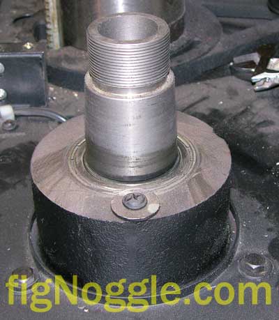
As you can see from the following picture, the pulley just press fits onto a tapered spindle:
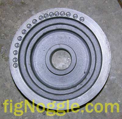
To remove the bearings, just remove the two screws securing the bearing and tap from the inside of the head. We didn't do this since it looked fine and you couldn't regrease these sealed bearings anyway. Here's a picture of the underside of the cast iron step pulley. Note the drill marks. We think this was to counterbalance the pulley to reduce vibration.
OK, now for the fun stuff! The only thing holding the quill in place is the quill lock (which only serves to clamp down the head to lock the quill in place) and the feed lever assembly. So we'll apply just a bit of clamping pressure to the quill to avoid it from plunking down onto the table (the other thing to do is to put a rag on the table and lower the head as far as you can). Remove the three-armed lever by simply unscrewing the plastic handlded lock screw. Next remove the two socket head cap screws from the base of the unit.
On the other side of the mill, you'll need to remove the spingback tensioner unit. Carefully loosen the lock nut and rotate the spring unit until the preload is removed. Do not worry about any springs popping out at you. This is a self-contained wind up spring mounted to the housing. After unwinding it, remove it.
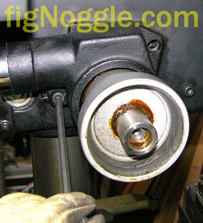
There's a little trick to removing it. The end of the spring has a notch in it that has one end with a hole large enough to go through the screw head that's behind the shaft (can't see it fro this picture). You'll need to rotate the housing until the spring mates with the hole so that it can be slid off the screw head and removed as shown above. Now, slide the entire assembly from the lever side until you pull this out (remember pay attention to your quill/spindle as it could just drop down due to gravity at this point):
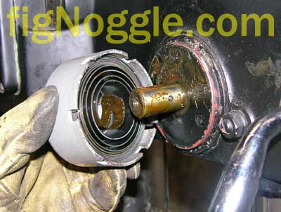
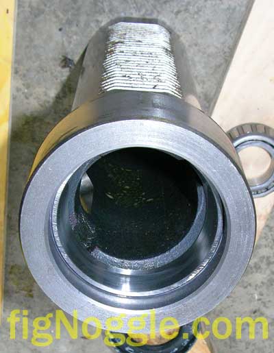
Look at the nicely crusted grease. Our guess is that it's original to the mill. Now it's time to slide the quill/spindle unit from the head. Simply raise the head until you have enough clearance to slide the unit out. Here's a picture of the keyway in the quill that prevents rotation. See that little set screw to the right of the spring unit? That's the screw that slides in the keyway channel to prevent rotation.
No need to remove the set screw. And we continue to slide the unit out from the head.
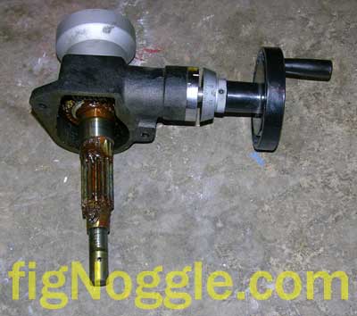
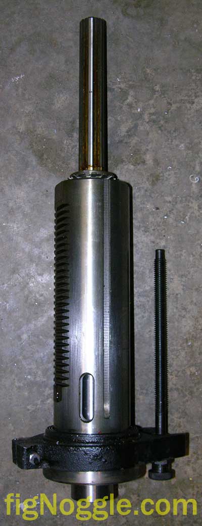
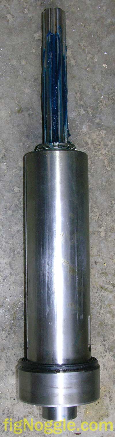
Here's what the unit looks like. Here's a thought.. As we're developing our CNC vertical mill project, we could also trade up and go with this larger unit. It would require some more work to fabricate brackets, but the added mass of this unit over the X2 mini mill spindle/head assembly could prove useful.
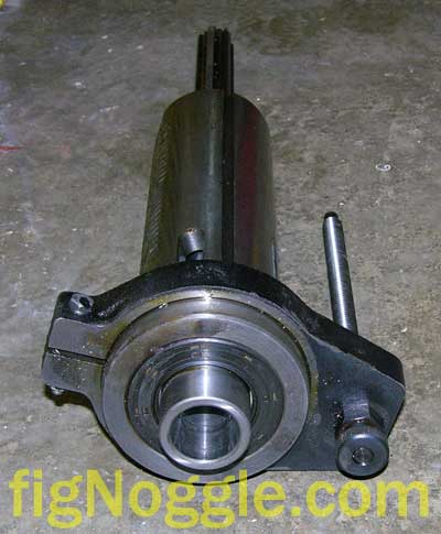
It's up to you if you want to remove the depth stop unit from the quill body. Here's another view of the same assemly:
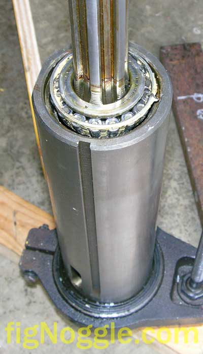
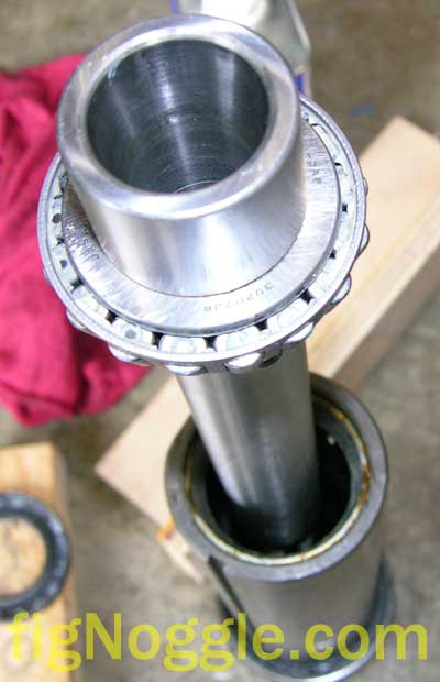
The black plastic ring around the spindle is the bearing cap cover. Once you remove the gunk that's glued it in place, you can simply just pull it from the spindle. You'll now need to undo the left-hand threaded retaining lock rings. No need for a spanner wrench (though useful). You can tap the notches with a flat head screwdriver until it starts to unseat. Chances are the top lock ring is already loose. And, you'll also need to undo the tab of the spider ring that's holding the lock nut in place. If you have an arbor press with enough length-wise capacity, you can simply press the spline end to push out the top tapered roller bearing and eject the spindle from the quill. Alternatively, you can set some blocks of wood underneath the quill and tap away at the spline with a rubber mallet/block of wood until the top bearing starts to unseat. Here's a top-view. Note the white lithium grease and that these are tapered roller bearings.
Once you fully remove the bearing, the other end will slide out with the bearing in tact.
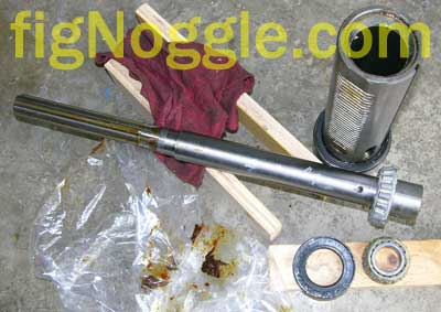
Here are all the pieces of the assembly:
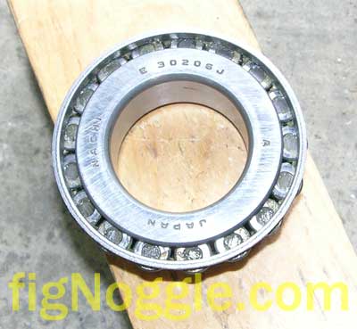
The brown gunk is the old grease. Very nasty stuff. The manufacturer used two different brand of tapered roller bearings. One is made from Koyo and the other made from Nachi.
The top one is a "Nachi E 30206J A" and the bottom is a "KOYO H-Cap 30207JR". We'll dig up some more specs on these later and post them here. And another shot of both. Note the socket head cap screw on the side of the spindle. That's the R8 keyway "guide".
Here's an interesting view of the inside of the quill race (table end) where the bearings make contact. It looks like light scoring/wear patch in the fore/aft (Y-axis). Does this mean that there was indeed some fore/aft play that could have caused this?
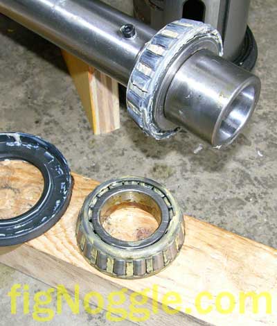
After cleaning and regreasing with XHP222 MOBILGREASE (blue lithium grease and it's probably too rich for this application), we reassembled the spindle and quill only to note more scoring on the quill body this time:
Note again the orientation of the scoring. It looks like the Y-axis is prone to play. This is most likely due to the fact that the split in thehousing is in the Y-axis and therefore creates the "opening" there for extra movement especially under loads. To match this scoring, note the inside of the casting and the two lines of gunk. It also appears in the Y-axis/plane.
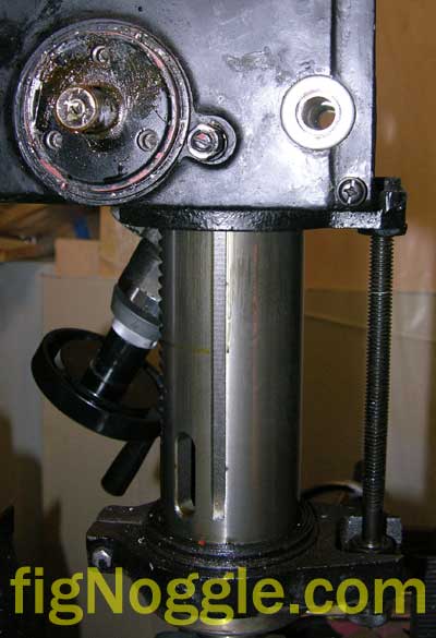
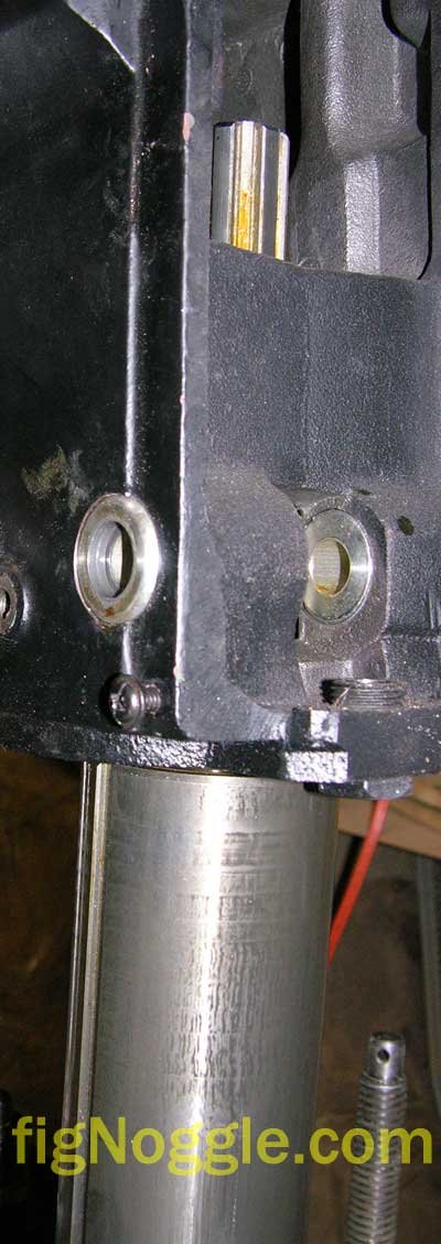
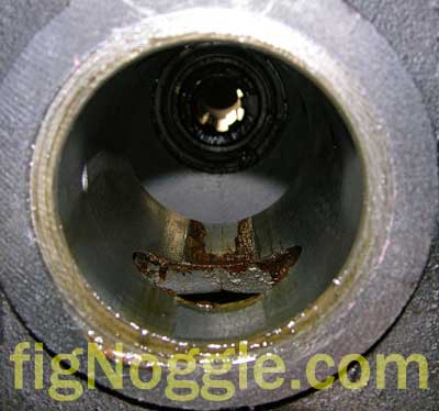
And the final shot of the mill - a view looking up into the quill casing:
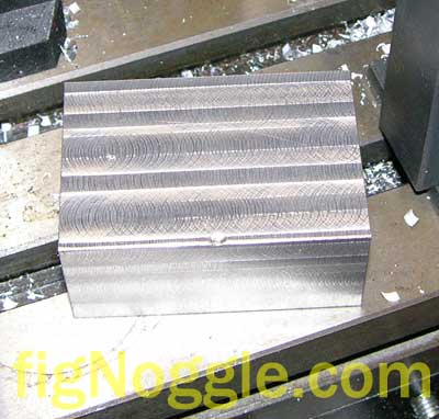
Note the gunk trail. Clearly, this is one cause of play if the quill is not locked down. But the contact patches indicate that the quill and head casing don't quite mate up. What does this ultimately mean? Perhaps nothing. After all this work, we took some light, slow cuts in an aluminum chunk. Did our surface finish improve?
We say no. In reality, the finish is more consistent (consistently not good, that is, but consistent none-the-less) which could indicate that we've actually eliminated that source of inconsistent finishes. Again, with a fly cutter, face mill, 4-flute end mill, all running at various combinations of depth of cut, speed/feed, we get the above. This now points us to the direction we've been neglecting all along - vibration. Wtih a dial test indicator mounted to a bar on the framing of the workshop and with the contact point touching the front of the table (sorry, no more juice in the camera), we started up the mill. The DTi vibrated and moved back and forth sweeping across zero in a very rhythmic pace. As it turns out, there's about two and a half thou (0.0025") of deflection caused by the motor vibration. This is most likely what is causing this unacceptable result. The only real final test now would be to mount another motor that gives off little to no vibration when run under no load (the Dayton/Grainger motor is the source of the vibration here) and see how surface finish is affected. Our educated guess at this point is that the results will improve dramatically and to a point where we can accept the mill as-is and produce quality parts. Another final note about this procedure. After running the mill for a few minutes we noticed that the spindle (where the taper is) was getting very warm to the touch. In some instances, hot enough to cause alarm (for example, when grabbed and held for more than a second or two). This would indicate that the grease used is incorrect for this application (too thick) and/or the preload set was too much. To adjust this, simply (without the quill removed this time) take the screwdriver and tap the lock nuts until the correct amount of preload is found. We probably should have used a white lithium grease since it's not as thick as the MobileGrease used. This may lead to yet another "quill pull" for us. As for vibration, we do need to stress that the column had already been filled with some cement compound (looks like some synthetic stuff) and this did not seem to have any effect on dampening vibration. This claim is untested since we did not use the mill sans colum-fill, but can say that if vibration is worse without the column filled, this mill has some serious design flaws! The verdict to date? Fenner belts help reduce vibration to the spindle which improves surface finishes. But the motor still can and does transmit vibration to the table. So, the motor needs to be addressed. If these prictures looked noticable better than the usual ones we use, it's because we swapped out the Canon S210 for a Nikon 8MP SLR-body point and shoot. Stay tuned...
|

Looking for mini-mill help and how-tos? How about lathe help and how-tos?
We're prototyping a benchtop CNC vertical mill using the DigiSpeed-XL interface card for Mach, Dart Controls and KB Electronics KBIC/KBMM 90VDC motor controllers, 1.5HP treadmill motor from Surplus Center and a R8-spindle head from the X2 mini-mill - not to mention Gecko servo drives and an entirely closed-loop system. Come take a look!CNC 8x12 Lathe
Check out our newest developments like the CNC/DRO 8x12/8x14 lathe using Gecko drives, break-out board, NEMA 34 step motors, DRO and more!
SUPERX3.COM
Sieg X3 and Super X3 Grizzly G0463 Info
MDAHacks.com
T-Mobile MDA / Cingular 8125 / HTC Wizard Hacks, Tweaks, Tips, Tricks and More!
Metal Working FAQ.NET
Your source for metalworking and machining, tips, tricks, and more. Over 50 content wiki sites!