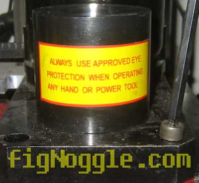
(239,’2006-08-10 12:00:00′,’figNoggle’,’2007-01-05 00:04:27′,’david’,’Sieg X2 Mini-Mill Belt Drive Conversion – Part 1′,”,’Finally the noise got to us. The gears amazingly have remained intact through some careful, though rough use with flycutters, 3/4″ end mills, cutting mild steel, aluminum and other strange things. It must be because we weren’t taking 1/2″ cuts at a time ![]()
That’s all fine, but when the mill is being used in CNC mode for hours at a time, the noise becomes unbearable. So while some other projects required re-tooling in the shop, we found this an opportune time to work on this belt drive conversion.
We had three basic design constraints: 1. can it be made using a lathe or mill itself prior to the conversion and 2. low-cost and 3. relatively easy to make.
Since turning v-belt pulleys takes some skill (especially if working with a smaller lathe like the 7×12 or even the 8×12), we wondered if we could use timing belt pulleys instead. There were already a few laying around in the shop, plus we like them better than v-pulleys.
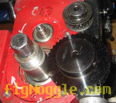
The first step was to remove the gear cover.
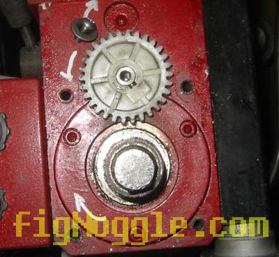
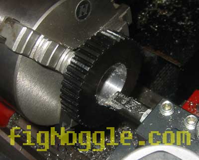
Next, remove the intermediate gear (one of the commonly broken ones):
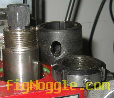
Next, using the two included spanner wrenches (they are sized differently so be sure to use the right one for the collar and the lock nut):
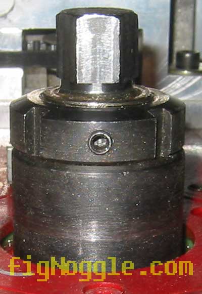
Now, remove the 5mm key and the collar and lock nut:
Now comes the fun part! We’re going to use a 1:2 gearing ratio which will give us a max speed of 000RPM based on the motor’s rated 000RPM. You may be wondering about being able to change speed ranges. We think for many milling operations using “regular” sized end mills and given the feed rates possible via manual and CNC on the mini-mill, simplicity of a single range should be fine.
We’ll need to drill and bore out the two shaft holes; the smaller for the 9mm motor shaft and 1.180″ for the spindle.
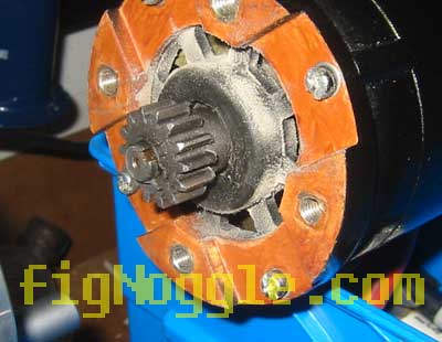
But first, remove the gear from the motor shaft (watch out for that flying circlip when you remove it!):
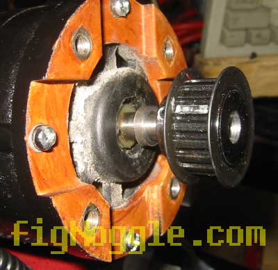
After drilling a 9MM hole into the smaller timing pulley (ours was mounted in the 8×12 lathe), you’ll also need to make a small spacer (which was also turned in the lathe) to offset the pulley from the motor shaft base. This also produces enough clearance:
Next, we’ll need to bore a hole to fit the spindle. It starts out with a 5/16″ hole:
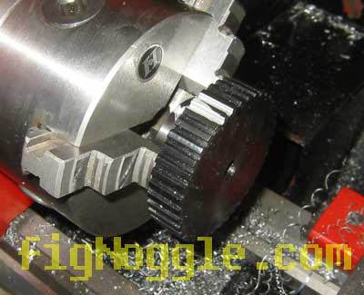
After a few passes at 0.020″, we end up with a really nice fitting bored hole:
This really was much easier to do in the 8×12 than with the 7×10 mini-lathe.
Now the mock-up assembly:

Some of you astute conversion-ists may be wondering where the spindle lock will go? We’re going to simplify things here and drill a hole right into the pulley vertically! More on this conversion coming shortly… Stay tuned!
And here’s part 2 of the series.‘
‘,’
Finally the noise got to us. The gears amazingly have remained intact through some careful, though rough use with flycutters, 3/4” end mills, cutting mild steel, aluminum and other strange things. It must be because we weren’t taking 1/2” cuts at a time ![]()
That’s all fine, but when the mill is being used in CNC mode for hours at a time, the noise becomes unbearable. So while some other projects required re-tooling in the shop, we found this an opportune time to work on this belt drive conversion.
We had three basic design constraints: 1. can it be made using a lathe or mill itself prior to the conversion and 2. low-cost and 3. relatively easy to make.
Since turning v-belt pulleys takes some skill (especially if working with a smaller lathe like the 7×12 or even the 8×12), we wondered if we could use timing belt pulleys instead. There were already a few laying around in the shop, plus we like them better than v-pulleys.
The first step was to remove the gear cover.
Next, remove the intermediate gear (one of the commonly broken ones):
Next, using the two included spanner wrenches (they are sized differently so be sure to use the right one for the collar and the lock nut):
Now, remove the 5mm key and the collar and lock nut:
Now comes the fun part! We’re going to use a 1:2 gearing ratio which will give us a max speed of 000RPM based on the motor’s rated 000RPM. You may be wondering about being able to change speed ranges. We think for many milling operations using “regular” sized end mills and given the feed rates possible via manual and CNC on the mini-mill, simplicity of a single range should be fine.
We’ll need to drill and bore out the two shaft holes; the smaller for the 9mm motor shaft and 1.180” for the spindle.
But first, remove the gear from the motor shaft (watch out for that flying circlip when you remove it!):
After drilling a 9MM hole into the smaller timing pulley (ours was mounted in the 8×12 lathe), you’ll also need to make a small spacer (which was also turned in the lathe) to offset the pulley from the motor shaft base. This also produces enough clearance:
Next, we’ll need to bore a hole to fit the spindle. It starts out with a 5/16” hole:
After a few passes at 0.020”, we end up with a really nice fitting bored hole:
This really was much easier to do in the 8×12 than with the 7×10 mini-lathe.
Now the mock-up assembly:
Some of you astute conversion-ists may be wondering where the spindle lock will go? We’re going to simplify things here and drill a hole right into the pulley vertically! More on this conversion coming shortly… Stay tuned!
And here’s part 2 of the series.‘
‘,’Finally the noise got to us. The gears amazingly have remained intact through some careful, though rough use with flycutters, 3/4″ end mills, cutting mild steel, aluminum and other strange things. It must be because we weren’t taking 1/2″ cuts at a time ![]()
That’s all fine, but when the mill is being used in CNC mode for hours at a time, the noise becomes unbearable. So while some other projects required re-tooling in the shop, we found this an opportune time to work on this belt drive conversion.
We had three basic design constraints: 1. can it be made using a lathe or mill itself prior to the conversion and 2. low-cost and 3. relatively easy to make.
Since turning v-belt pulleys takes some skill (especially if working with a smaller lathe like the 7×12 or even the 8×12), we wondered if we could use timing belt pulleys instead. There were already a few laying around in the shop, plus we like them better than v-pulleys.
‘,’
Finally the noise got to us. The gears amazingly have remained intact through some careful, though rough use with flycutters, 3/4” end mills, cutting mild steel, aluminum and other strange things. It must be because we weren’t taking 1/2” cuts at a time ![]()
That’s all fine, but when the mill is being used in CNC mode for hours at a time, the noise becomes unbearable. So while some other projects required re-tooling in the shop, we found this an opportune time to work on this belt drive conversion.
We had three basic design constraints: 1. can it be made using a lathe or mill itself prior to the conversion and 2. low-cost and 3. relatively easy to make.
Since turning v-belt pulleys takes some skill (especially if working with a smaller lathe like the 7×12 or even the 8×12), we wondered if we could use timing belt pulleys instead. There were already a few laying around in the shop, plus we like them better than v-pulleys.
‘,”,’Sieg-X2-Mini-Mill’,”,0,”,0,4,1,1,’article’,”,”,’sieg-x2-mini-mill-belt-drive-conversion-part-1′,”,”,”,”,”,”,”,”,”,”,’b7ed1ec2f429f591adb35298b28ec8da’,’2006-08-10′);