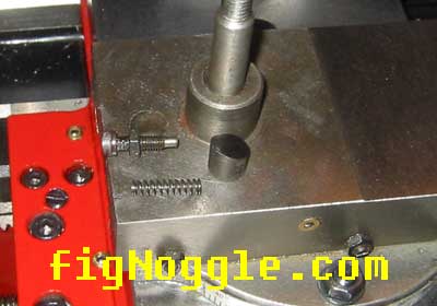
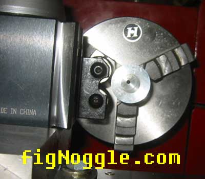
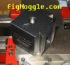
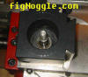
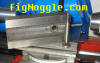
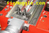
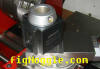
| remove the detent mechanism from the toolpost slide
by removing the screw and nut holding the spring and notch bit in place. |
 |
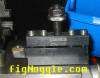
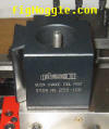
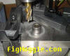
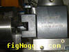
| remove the post and two screws holding the plunger
nuts. |
 |
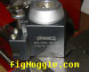
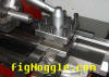
| insert a 8x32 screw into each of the plunger nuts.
flip the unit upside down and pull nuts outwards.
the eccentric unit should drop out. |
 |
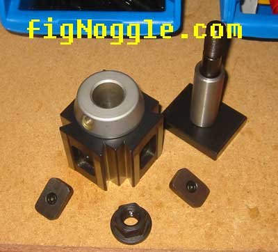
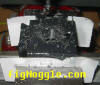
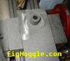
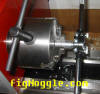
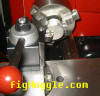
| here are the parts. |
 |
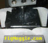
| take appropriate measurements.
here we are testing clearance.
the bottom of the base will need to be machined
larger to accommodate the existing flange on the compound slide.
we do this because it is not only easier to
machine the toolpost base than the compound slide base, buying replacement
stock parts for the lathe may prove difficult. the flange would also not
have enough material remaining if we were to machine it down to the
diameter of the toolpost base. |
 |
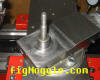
| here is a 1/2" toolbit in a holder. |
 |
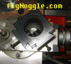
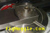
| we are centering the toolpost base in the mini mill
since there's no 4-jaw chuck to use.
we are
using the wiggler
method for finding our center. |
 |
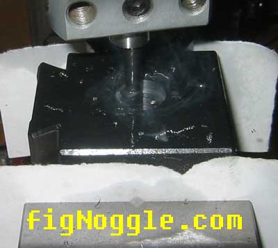
| here's some WD40 smoke (yes, we should have used
something else)
what nice about having a CNC
conversion WITH manual is that we can rough everything by using the stock
handles to move the boring head up and down.
in the final passes, we set Mach to move the
Z-axis motor very slowly so that we use it like an auto-feed. (that's why
our cnc conversion plans keep
manual functionality!) |
 |
| here's quick video clip of it in action.
the speed and feed were too fast. |
click to see
video |
| here are the chips.
each pass was made at 0.005" for a 0.010" diameter
cut. |
 |
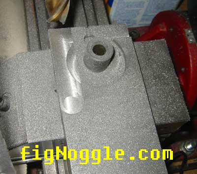
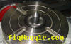
| this is a really nice fit. no play, nice slip fit.
here you can see the inside of the stock post which
we'll keep. it's just a tad higher than the top of the newly bored hole. |
 |
| here it's sitting flush on the compound slide. |
 |
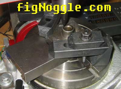
| we need to check our clearances again.
note that the bit holder is resting on the compound
slide.
see anything wrong here? the bit's too high. |
 |
| we're off by 0.100" or so.
question is which part do we remove material from?
the tool holders or the compound slide?
i see that lathemaster has removed material from his compound slide. (it's
certainly the quickest and perhaps best work-around?) |
 |
| should we decide to also go this route, we need to
check for clearance if we rotate the toolpost.
here's a sharpie pen line showing us how much to
remove. |
 |
| it's been decided that the compound will be machined
down to accept the QCTP. imagine the amount of work needed to machine down
each of the toolholders (including knurling, parting and boring bar
holders)..
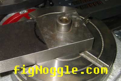
here is the compound toolpost
taken out. note the locating pin. |
 |
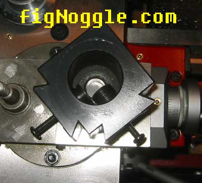
| the compound it getting ready for machining. |
 |
| first we centered the rotary
table on the mill (the lathe's swing is too small to chuck it in
there).
we thought we could just use the MT2
dead center as a locating jig but the height is off.
we made one that works really well! (we may be
offering plans for this shortly). it's great when you need to quickly
center a workpiece that has an existing hole. our model was accurate to
+/-0.002". not too bad. |
 |
| the compound is centered and clamped. |
 |
| during some recent operations that required
rotating the compound, the two bolts' threads were stripped.. |
 |
| the two stock t-bolts were hacked and the bottom
parts were re-used.
a simple, drill and tap allowed us to slip in two
1/4"x20 thread.
now it works great. |
 |
| before we continue, here's how much actual room you
have to work with with the 8x12/14 (8"x12" / 8"x14") lathe.
not a heck of a lot when a drill bit is chucked in
there.
still, it beats the 7x10 hands-down. |
 |
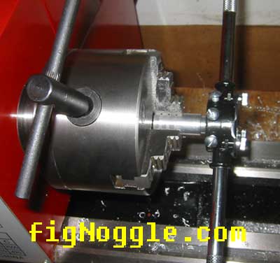
| back to regularly scheduled programming...
we are taking our first cuts into the compound with
it mounted and centered! using our jig on the rotary table. |
 |
| cast iron makes some nasty dust.
we're milling the remaining area. |
 |
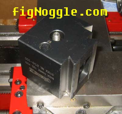
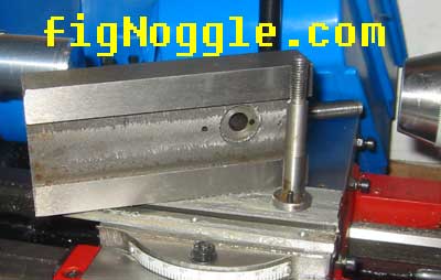
| here's the compound, completed!
we cut roughly .150" from the compound.
the old screw hole for the locating pin is
essentially gone. |
 |
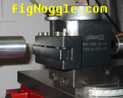
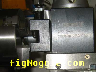
| here's a test fit of the phase 2 quick change tool
post on the compound.
still fits like a
glove. |
 |
| now we're taking some time to play with the
adjustments to make sure there's plenty of clearance.
note the position of the knurling attachment. |
 |
| here it is in reference to a workpiece. low. |
 |
| this means we can move the attachment up to center
it. |
 |
| now it's time to get started with retrofit and
modification of various parts to get the qctp mounted.
note that the sleeve is too long. we'll need to
shorten it quite a bit. |
 |
| here we're working on some integral parts.
since the compound was milled down, we needed to
bring the height back up for the turret toolpost.
we used parallels. |
 |
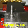
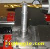
| this is close!
we're
parting off a piece of the toolpost extension. |
 |
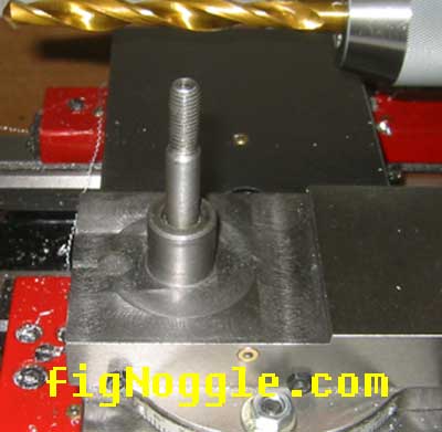
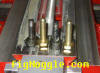
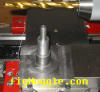
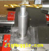
| now we're threading a 1/2"x13tpi die on the
extension.
see the bands on the workpiece?
there's so much torque being applied that the chuck couldn't hold it.
that large threading operation was a tough one. |
 |
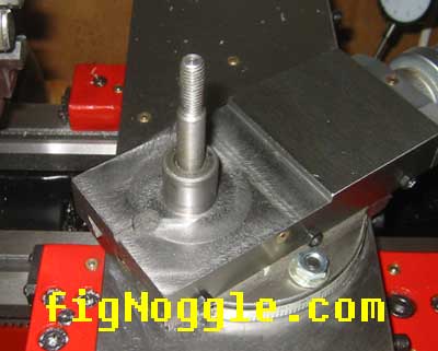
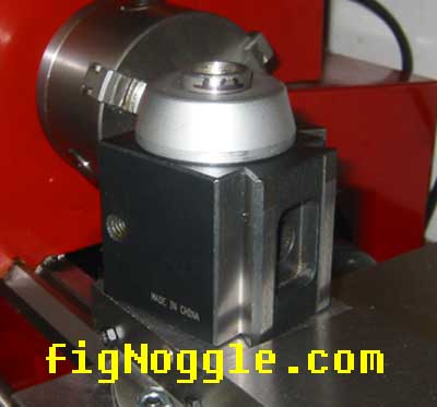
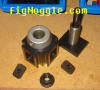
| here's the toolpost assembly in four easy steps.
step 1. stock toolpost. |
 |
| step 2. add the spacer sleeve. |
 |
| step 3. add the threaded extension. if we had a
longer tap, we could have made this all one piece. |
 |
| step 4. the stock qctp sleeve (which also had to have
a small relief cut out from the inside) fitted over the extension. |
 |
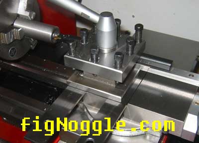
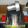
| the entire assembly mounted and cutting!
here's a shiny face cut. note that it's centered
perfectly.
this upgrade definitely took some time. the
process is not trivial and required some good mental work in dimensioning.
this is actually just a prototype as the extension
pieces were made of aluminum.
the real (next) version will be made with steel.
in order to perform this operation, you'll need
either a lathe with a large swing (to swing the compound around) and/or a
mill (in this case a mini mill with a rotary table).
centering the compound was easy since we had made
a jig to center it. as it turns out, it's quite accurate as you can see
from the cut around the toolpost. |
 |