(269,’2007-02-04 23:19:24′,’david’,’2007-02-07 09:50:36′,’david’,’8×12/8×14 Lathe Hybrid Follow Rest / Moving “Steady” Rest – Day 2′,”,’After the first day creating the “T” assembly of the hybrid follow/steady rest, we figure that the easiest way to complete this project (it’s just a prototype) is to quickly make a plate with a bored out circular hole to allow for the diameter of a larger workpiece and have the three “fingers” with attached ball bearings mount to this plate. Finally, the plate would be attached with slots for vertical mounting and adjustment to the “T” vertical post.
Luckily for us, we already had a plate with a bored hole that was one of the first prototypes of the X-axis NEMA 23 mounting plate for the X2 mini-mill CNC conversion. We still needed to bore the hole larger than the 1.5″ or so that was already there.

One thing we keep forgetting to mention is the poor quality of the “dykem” marking paint (the blue you see) from ENCO. The problem with their brand of dye is that it doesn’t “stick” to the material and acts like the material has grease spots on it. Also, the can it comes in gets stuck after the first few uses. Very frustrating to use.
Back to the project…
We didn’t take “action shots” of the various pieces being milled. One point of interest is that while we’re having problems with the finish of workpieces using the Dayton/Grainger (aka RF-31) round column mill, boring operations have excellent finishes far superior than the X2 mini-mill. This indiciates to us that the quill indeed has some slop in it and will probably need its bearings regreased and adjusted.
Back to the project…
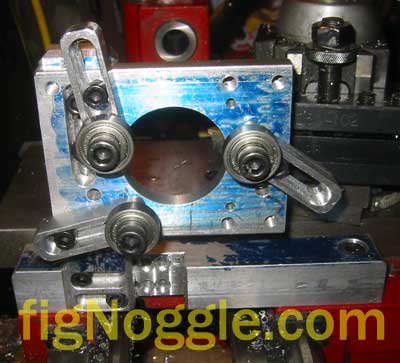
After drilling and tapping more 1/4″ x 20 holes in the vertical post and milling slots in the plate, we also drilled and tapped a few holes for the 3 fingers. The 3 fingers are nothing more than some rounded-edges stock with slots in them for adjustability to the plate and a single 5/16″ x 18tpi threaded hole for the ball bearing.
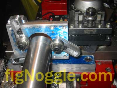
After all that work, you can see the tailstock view of the assembly with a piece of 1.5″ diameter steel rod used for the injection molding barrel/nozzle assembly inserted in the chuck and through the rest.
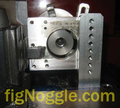
Note the holes in the post. This basically allows for a reasonable amount of “infinite” adjustability in the vertical direction.
All that’s needed to make the hybrid steady/follow rest work is to generally position it such that the workpiece is centered in the plate. Then, adjust each of the fingers such that the bearings touch the circumference of the workpiece at roughly 120 degree points (360/3) and tighten down the socket head cap screws.

And a top view of the same:
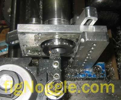
Now, it’s time to test it!
The reason for this entire project was to be able to bore a larger diameter hole without causing the workpiece to runout from true. It works!
This project in total took about a half day of work. This is again a prototype and will definitely need some refinements. It does, however, serve its purpose. One problem encountered after some hard turning is that the grease in the ball bearings just about wore out. Perhaps a better bearing is the use of needle bearings which we had but would have required some more work. This will be the next modification to the design. The other advantage to using needle bearings is that they’re wider to begin with, thereby increasing the contact patch with the workpiece.
Stay tuned for more updates on this project.
‘,’
After the first day creating the “T” assembly of the hybrid follow/steady rest, we figure that the easiest way to complete this project (it’s just a prototype) is to quickly make a plate with a bored out circular hole to allow for the diameter of a larger workpiece and have the three “fingers” with attached ball bearings mount to this plate. Finally, the plate would be attached with slots for vertical mounting and adjustment to the “T” vertical post.
Luckily for us, we already had a plate with a bored hole that was one of the first prototypes of the X-axis NEMA 23 mounting plate for the X2 mini-mill CNC conversion. We still needed to bore the hole larger than the 1.5” or so that was already there.
One thing we keep forgetting to mention is the poor quality of the “dykem” marking paint (the blue you see) from ENCO. The problem with their brand of dye is that it doesn’t “stick” to the material and acts like the material has grease spots on it. Also, the can it comes in gets stuck after the first few uses. Very frustrating to use.
Back to the project…
We didn’t take “action shots” of the various pieces being milled. One point of interest is that while we’re having problems with the finish of workpieces using the Dayton/Grainger (aka RF-31) round column mill, boring operations have excellent finishes far superior than the X2 mini-mill. This indiciates to us that the quill indeed has some slop in it and will probably need its bearings regreased and adjusted.
Back to the project…
After drilling and tapping more 1/4” x 20 holes in the vertical post and milling slots in the plate, we also drilled and tapped a few holes for the 3 fingers. The 3 fingers are nothing more than some rounded-edges stock with slots in them for adjustability to the plate and a single 5/16” x 18tpi threaded hole for the ball bearing.
After all that work, you can see the tailstock view of the assembly with a piece of 1.5” diameter steel rod used for the injection molding barrel/nozzle assembly inserted in the chuck and through the rest.
Note the holes in the post. This basically allows for a reasonable amount of “infinite” adjustability in the vertical direction.
All that’s needed to make the hybrid steady/follow rest work is to generally position it such that the workpiece is centered in the plate. Then, adjust each of the fingers such that the bearings touch the circumference of the workpiece at roughly 120 degree points (360/3) and tighten down the socket head cap screws.
And a top view of the same:
Now, it’s time to test it!
The reason for this entire project was to be able to bore a larger diameter hole without causing the workpiece to runout from true. It works!
This project in total took about a half day of work. This is again a prototype and will definitely need some refinements. It does, however, serve its purpose. One problem encountered after some hard turning is that the grease in the ball bearings just about wore out. Perhaps a better bearing is the use of needle bearings which we had but would have required some more work. This will be the next modification to the design. The other advantage to using needle bearings is that they’re wider to begin with, thereby increasing the contact patch with the workpiece.
Stay tuned for more updates on this project.
‘,’After the first day creating the “T” assembly of the hybrid follow/steady rest, we figure that the easiest way to complete this project (it’s just a prototype) is to quickly make a plate with a bored out circular hole to allow for the diameter of a larger workpiece and have the three “fingers” with attached ball bearings mount to this plate. Finally, the plate would be attached with slots for vertical mounting and adjustment to the “T” vertical post.
‘,’
After the first day creating the “T” assembly of the hybrid follow/steady rest, we figure that the easiest way to complete this project (it’s just a prototype) is to quickly make a plate with a bored out circular hole to allow for the diameter of a larger workpiece and have the three “fingers” with attached ball bearings mount to this plate. Finally, the plate would be attached with slots for vertical mounting and adjustment to the “T” vertical post.
‘,”,’8x128x14-Small-Lathe’,”,1,’Comment’,0,4,1,1,’article’,”,”,’8x128x14-lathe-hybrid-follow-rest-moving-steady-rest-day-2′,”,”,”,”,”,”,”,”,”,”,’6b7f6a05ba134825c626e2da11b50cec’,’2007-02-04′);