A
14" bed extension kit was ordered from Chis Woods at Little Machine
Shop, part # 1928. Nearly all critical machined surfaces had some
rather thick paint slopped about on them and this would have to go. The
worst of it was in the
area inside the webbing where
the tail stock would register. Stripping required. First
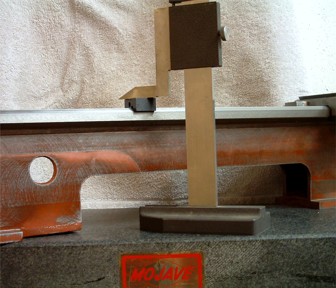
a critical dimensional check. The beds are ground so a point of
reference for the grinder is needed and this would be the foot area. This makes
it fairly straight forward to qualify the casting by placing it on a
surface plate first checking for rock, indicating a twist and
using a height gauge checking for bow or warp and flat/level relative to
the surface plate and the "V" way relative to the flat
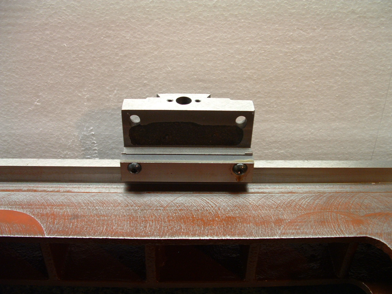
way. The "V" requires multiple checks as angles are involved and the top
of the "V" in truncated. This was done with the top half of
a bed lock as shown in the photo below. Once
the "V" is qualified then direct micrometer measurement from the
top of the "V" to the lower bearing area for the saddle gib area is assured.
If the "V" is not qualified then the bed lock block and micrometer is
required for thickness checks.
This bed checked out dead
flat and all relative positions in alignment except that the lower
bearing block area for the saddle
gibs, which are milled and
not ground, displayed slight thickness variations which will be
corrected latter when the saddle is
fit to the bed.
After
the checks were done the entire bed was stripped inside and out.
Machined exterior surfaces were masked with Duct Tape to prevent nicks
and dings while the rough handling was going on, there is no gentile way
to do this. A spray type stripper for epoxies was
used as gel types were quite ineffective. Small brass bristle brushes
were required in the rough areas of the internal
webbing and motor mount areas and repeated coats required even then. A
good washing in a bucket of mineral spirits
followed as well as allot of fine filing of the burrs and sharp
edges. No serious voids were
uncovered but a good deal of casting sand was eliminated during this
step. The part, sand cast, uses about a dozen cores,
none of which line up well. Ergo there is a good deal of very soft
filler used in the worst areas. As you can see from the photo
just to the left of the height gauge most surfaces not ground or left
natural, are fly milled and not gently. None of
the red you see in the photo was present after stripping. This is a thin
coat of auto body glaze after sanding with a block
sander. The interior of the webbing and motor mount areas are already
painted with Glyptal electric motor insulating
paint. It's tough and quite resistant to oils. Painting the interior is a
very tedious task and very time consuming. Masking the machined areas is
nearly impossible so a
steady hand, small art
brushes, lots of angles of attack are the weapons to prevent re-coating
the areas you just spent so
much time
stripping. The bed as delivered weighed
in at 25 lbs. After stripping and knocking sand out of it and removing
soft fillers, 24 lbs. The 14" beds have
several more internal webs and the right foot is fully cast unlike my
short bed machine. The motor mount area is wider to
accommodate the larger motors normally fit to these machines as well.
Both feet of the casting are also
longer. With the bed initial
preparation completed and measurements qualified the next task is to fit
the saddle assembly. Don't under estimate the
importance of all the detail work. Everything references from the bed of
the machine, if it isn't right, nothing else
will be either. T'is the very foundation of your
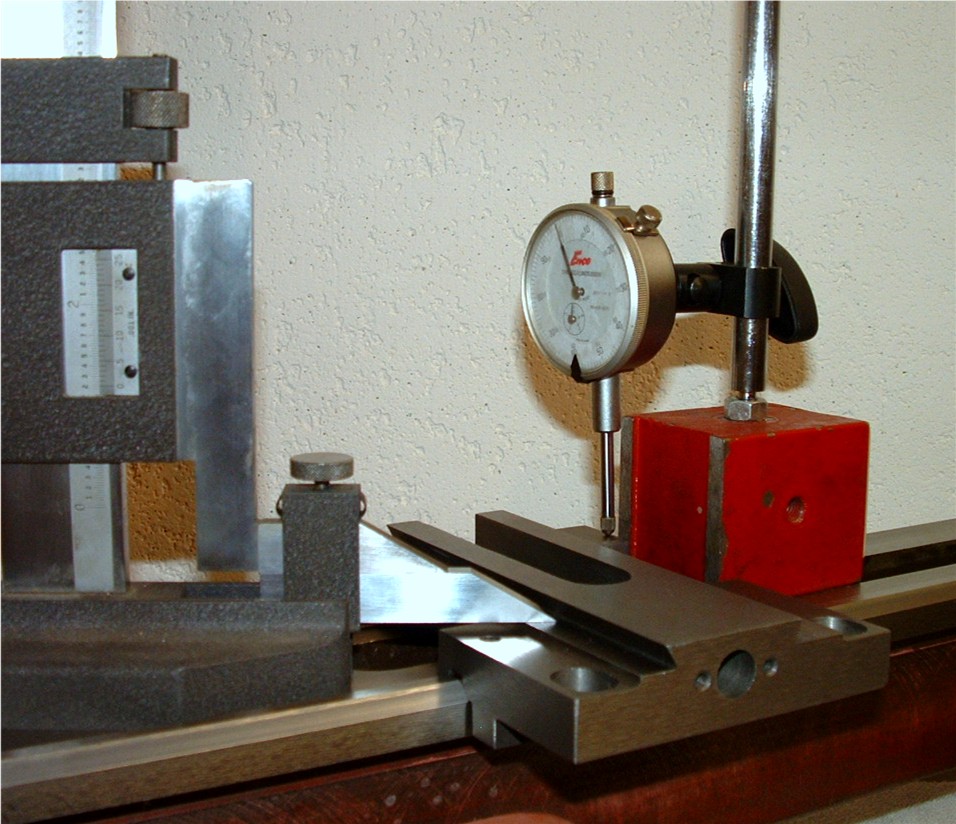
project. Using
the height gauge a near side reference is marked to locate it in the
same position each time. Height is set from the base of the compound dove
register as this is referenced not only to the bed but will be the
reference for the compound later when fitted. Note
I used the gauge foot extension to do this to get as much distance
between points as possible. Once zero is set the height
gauge is rotated to the back . A dial indicator on magnetic base set and
zeroed. Now pressure is
placed upon the near side of
the saddle (operator side) using the "V" as the fulcrum which will lift
the back side until it contacts the height gauge and
down hill distance can now be read directly from the dial indicator.
When this was first done the back of the saddle was
.018" lower than the front! The
height gauge can be moved to the opposite side to detect difference in
compound dove base height. In this case a few thou in
difference. Next
the measurement equipment is removed form the bed and finger pressure
applied to opposite corners, such as front left and right rear to
detect any tendency to rock and there was. Use of the dial indicator or
a feeler gauge can quantify the amount. Roughly
.005" in this case. Next
one must identify the high spots and points of contact. Layout die
applied to the saddle "V" and back flat and then setting it on the bed and
sliding it back a forth a few inches will mark those
places. As
side to side was pretty close I assumed the "V" to be pretty close in
that plane if but considerably high and the major problem area to be the
back flat. As it turned out the "V" area was making contact on both
sides but with little area in contact. The back
flat however removed next to nothing of the bluing. Just a light pencil
lead width concentrated on the high corner. As it was
so far out I used a medium sized second cut file to knock it down. Easy,
a few licks at a time and checking. This whole
process is slow and painful. Once the rocking motion was close to nil a
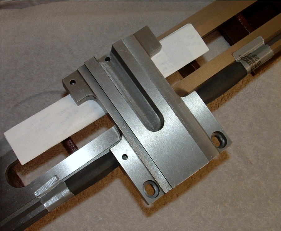
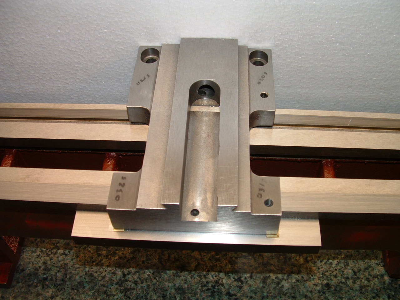
piece of wet/dry paper, 80 grit was placed
grit side up on the bed under the flat. A piece of paper over the "V" to
protect it and the saddle worked over this until all
trace of rock was removed. (Reverse of the top right picture) Of course
this makes the down hill condition even worse but full
line contact made across the flat which also corrected the side to side
difference for compound
dove
register. I
had Kresser Machine run a quarter inch end mill down the roof of the
"V". The reason this is needed is that the top flat of the "V" is about .200" wide
(6 mm) and the relief in the roof of the "V" is but .157" wide (4 mm).
As you attempt to remove material from this area to
lower the saddle a ridge is formed that prevents progress. To be honest
I didn't do this procedure
straight away but it came as
a consequence after working this thing silly for a week with little
progress. A bit more thought on
this and the roof height
would remain as is as it is the width I was after. Okay
so now we have the rock out, side to side squared up and some room in
the "V" to work with, now the hard part. Wet/Dry paper is cut to width
to just cover the "V" and Duct Taped in place and WD-40 applied before
the saddle is set down on it. On the flat
several folds of paper are placed between the saddle and the
flat. The
paper not only protects the un-lubricated flat but adjust the height. If
you don't shim it like this or make some other provision for height then as
you sand the saddle "V" it will eventually take a new angle and not one
you want. This takes awhile to get a feel
for, allot of tape and allot of sand paper and allot of paper towels
allot of solvent and a lot of patience. Work slow and
measure often as was done in the beginning. How many sheets of
paper? Well a sheet is about .003: thick and were
down about .021" at present plus the thickness of the sand paper so
roughly eight ply will be close and close at this
point is good enough. You want to be slightly high on the side your
working and work it until your slightly low, then
remove a single shim and do it again. Measure,
measure, measure...this took about an hour a night for nearly two weeks.
Measurements will help you get a feel for pressure, how many
strokes to remove how much metal, what grade paper to use and so on.
Nothing I can give implicit instructions
too and each case will be different. When
you get down to less than say .005" on the down hill trade the shim
stock for a sheet of wet/dry on the back and do the same on the front,
trade sand paper for a paper shim. You've reduced the angle enough to
get much better contact and now you need it
flat. Work both sides using a courser grade on the "V" than the flat.
You'll get a feel for how much, where and when to quit
long before your in trouble. (Remember, grit side up
:) If
you got all this, by now your within .0005" or so of down hill, no
rocking motion, both sides within .0005" in height
and using something in the
neighborhood of 320 grit paper. At
this point it just wiggles the dial indicator so I gave both sides a few
strokes with a sheet of 1500 grit, then cleaned and again with 2000 grit,
both with a liberal spray of mineral spirits and cleaned a final
time. When
finished I had full contact on all contact surfaces that would remove
blue (actually a Sharpie at this point) on a single passing. When wet with
WD-40 I placed the saddle at one end of the bed and gave it a tap. Don't
do that, it slid like a puck on an air hockey
table crashing off the opposite end onto the bench putting a ding in the
saddle that fortunately for me was in a
place of no harm. Now WD-40 isn't the normal oil to use on the bed
and heavier oil does induce more friction and the
slide is less free. Acts like a joy block actually. Slides freely but
near impossible to pull straight off the bed. When I
was close the dial indicator was replaced with a test indicator with
four decimal resolution and I ended with a wiggle in
the indicator for down hill. Under .0002 side to side and zero rocking
motion. Rechecking with the height gauge on all
surfaces and re-qualifying the "V" with the bed lock block produced no
measurable differences. The
finer and flatter the finish, the more precise the alignment (with the
appropriate lubrication) the tighter things like gibs can be set
limiting motion and precluding chatter and the lighter the oil that can
be used. Joy block type finishes actually help
dampen vibration using the elastic nature of the fluid as a shock
absorber. Such surfaces wear at a much lower rate due
to low contact unit loading. Now, this is what I've done
and I won't preach that as gospel to anyone. IF you disagree finish to
what you like and use what lubricants you like,
just get it flat and square and well aligned. Your now caught up
to the current state of the build. 3/22/2007
Rereading some of this I see I miss explanation of a very important
step. Cleaning up the dimensional differences of the bed
underside gib contact area. This was done by making measurements along
the way both front and back in half inch
increments writing the dimensions with felt marker on the bed. Using a
4" second cut flat file the high areas were taken down as
far as I dared. The the file wrapped in wet/dry 320 and worked until I
was within .0002", This took
several days and allot of measurements. I was concerned about getting
out of square but gentle pressure working short areas
at a time seemed to work just fine, even with out a guide fixture. Now
the ends of the bed on both ends taper to a
smaller dimension that the area I worked but I reasoned that only the
area covered by saddle travel need be worked
over. Later during gib fitting I used yet another method to finish the
underside to an immeasurable
tolerance. 3/17/2007 Rear
Gib
Front
Gib I
made the gibs close to my own drawings from A-2 house scraps
except thicker .350", and omitting the center hole. That made it 3.15" between
centers on the two remaining holes. The manufacture of the
gibs was very straight forward and went off without a hitch. Installing
them was another matter. I bought some brass
shim stock and a set of feeler gauges to sacrifice for same. I also
acquired a few sheets of 320 grit orbital
sander media with the sticky back like they use in body shops. This
turned out the be a very good idea. Nothing is
square on these machines and the gib registers were no different. Use of
a single shim proved unworkable as the
registers are .001" out of parallel with the bed end for end. This
translates into one end contacting the bed and the
other quite loose making the gib dig into the bed. I reasoned at this
point the two shims moved outboard of the
fasteners of different thicknesses might work quite nicely and it did.
Once it got it pretty close I disassembled the unit
again as I had yet a few tight spots here and there. Using the gib as a
template I cut sections of the sand paper
the full length and width of the gib and applied it sticky side to gib,
grit to bed and reinstalled the shims.
Running the saddle up and down the bed then hits only the high spots. If
you remember I had it down to about .0002"
to begin with but when you get things this close even that is too much.
Both front and back are now with in .00005
to .0001"" flat and parallel to that same dimension from the top of the
bed and that is as fine as I can
measure. High spots gone
the saddle fit a tad loose again so the shim packs were thinned a bit
more. Thing is that sometimes you need a shim in
some size other than standard .0005" increments. That's where the brass
stock, a lapping plate and some 2000
grit wet/dry earns its keep. Now anyone who has ever done a bit of this
close work would tell you that even bolt
tension will move things a bit and the idea is to get a shim that allows
enough torque to be applied to it to
prevent loosening during use and that takes a bit of trial and error, I
remade shims more than once. I might mention that
clean is highly important as well as at this level of fit even dust on a
shim makes or brakes it. I use brake
cleaner and lint free rags. Oil has thickness so it need be cleaned and
oiled each assembly cycle with the oil you are
committed to. I'm committed to ISO 68 way oil and the supplier is
unimportant but use the same one. I
remade a rear gib and made it 6" long X .4555" thick and 1.030" wide.
Only the length contributes to contact area however. Extra
thickness for the extra length for stiffness and width because I was too
rushed to mill it off. This time I also used
all three holes and located two stand off set screws as per original
except that they are centered perfectly and in
line with the three hold downs. These were made 1/4-20. Upon
installation I fit the center bolt, placed the shims as
before on the outside corners for level and gap. Then fit the two
outside caps and played the bolt tension until
satisfied. NOW I ran the set screws in to make firm contact and
tightened the lock nuts. Finally, as both sides of
each retaining screw are now supported those can be tightened to a
sufficient level to remain in
place. The difference is
night and day. Stick is gone and slip is even better. You would have to
feel it to know what I mean and I don't think a
video would make the point. A test indicator on the back shows ZERO
displacement of saddle to bed and something
under .0005" on the front. Placing and inclinometer on the bed and
elevating until the saddle moved gave a slip
angle of 7 degrees for a frictional coefficient of .121 "stick" and
maintained motion once underway to a 5 degrees
slip angle for a friction coefficient of .089. This is about a 4/5
reduction from factory in dynamic
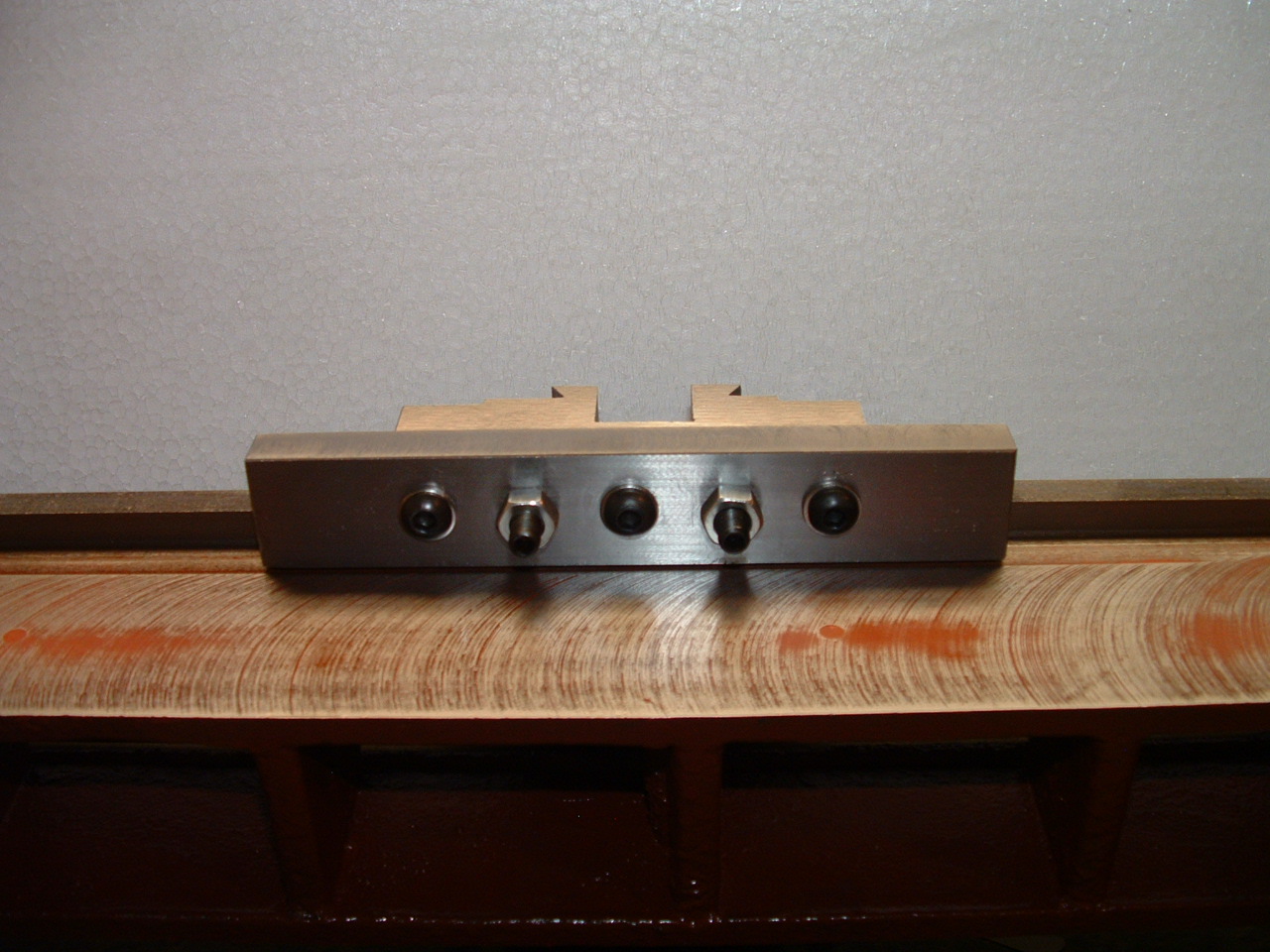
friction. Note: the shims widely spaced and
not full length but they are full width to prevent rocking. The
rough measurement for shim
thickness is above each but a bit of fine tuning on a sheet of 2000 grit
with thinning in increments of .0001" per
fitting was required to get it right. Of course that means I had to make
each one twice and you over shoot the dimension
one step the first pass. The different thickness is required as the
saddle casting is not parallel to the bed at
their mounting face. The
six inch length was a vast improvement over the standard 3.9" stock and
4" X .352" thick version. The extra length will preclude the use
of the motor guard but I don't plan on the stock location for the motor
anyway. Note
that the area for the cross slide screw is milled out in anticipation of
a thrust bearing in the collar later. The extra length is .250" and the
slot width is .804" provided by a reground 7/8 end mill which was the
closest thing to a 20 mm in the shop. While I
touched of the mill to go no deeper than .002" than the existing floor
of the channel the extra length broke through
the "V" roof which was raised .025" and widened .250" to drop the saddle
earlier to get the cross slide dove rails
level to bed. I could have gone back further as other have but I want to
keep the tool inside the rails. I will epoxy a
disc in this location to prevent chips from entering the "V" channel as
this become exposed when the slide is extended
with the bearing modifications. Note the even oil film on the
back way? Full and flat contact! Fully adjusted this saddle will slide
right off the end of the bed and go right back on
without a hitch with even light drag all the way to the head stock area
even though it's fit to near zero
gap. Several
notes in this view. Note how close I got the gib width to the bed
casting? It's all about stiffness and surface area, especially on
the rear gib. I will shorten the stand offs latter now that I have the
shim pack sorted and add some thin washers under
the jamb nuts as I did the button heads. Before you
ask, yes the apron will bolt up flush BUT the rack pinion will not
rotate. Instead of creating a stress riser by carving on it as the
taper gib arrangement does, I will turn the excess width from the gear.
It's about twice as wide as the rack and the
shaft proper does clear this fit buy .002" Button
heads again for a cleaner look and a bit more room. The stock caps are 6
mm X 12 mm at 1 mm pitch. These front caps are 16 mm
long and the rear ones 20 mm long with 1.5 mm thick washers. That may be
useful, right? The stand off on the
rear gib are 1/4 X 1 at 20 TPI. Don't worry about the coarseness
of the thread. You don't use them in this set up for
adjustment, only support and stiffness. When you get things this
aligned and use a good lube it is just magic what happens. I wish there
was some way to show or demonstrate
this on a web page. Top
View, Rear Gib
We're prototyping a benchtop CNC vertical mill using the DigiSpeed-XL interface card for Mach, Dart Controls and KB Electronics KBIC/KBMM 90VDC motor controllers, 1.5HP treadmill motor from Surplus Center and a R8-spindle head from the X2 mini-mill - not to mention Gecko servo drives and an entirely closed-loop system. Come take a look!
CNC 8x12 Lathe Check out our newest developments like the CNC/DRO 8x12/8x14 lathe using Gecko drives, break-out board, NEMA 34 step motors, DRO and more!
SUPERX3.COM
Sieg X3 and Super X3 Grizzly G0463 Info