
Copyright 2011. figNoggle Designs.
7x10, 7x12, 7x14 Mini-Lathe Information
Website Links
Post a link to your website or view other hobby and machine and metalworking websites for free.
|
Rent Mill & Lathe DVDs at Smartflix | Great aluminum & steel prices at OnlineMetals
7x10, 7x12, 7x14 MINI-LATHE7x12 Mini-Lathe 
 As you can see from
the photo I didn't take quite that much.
Before this operation I double checked the parallelism of the doves by measuring across a pair of linear guide rods pirated from a discarded lab device from work. The photo below is a mock up of that operation. Measurements are taken at each end and need be pretty close. This saddle is .0003" and yes you can feel that small amount. If you remember the height of the dove register was checked earlier when fitting the saddle and was spot on. There is always a risk of upsetting that measurement when lapping anything, if a lot of care isn't taken and constant checks made. 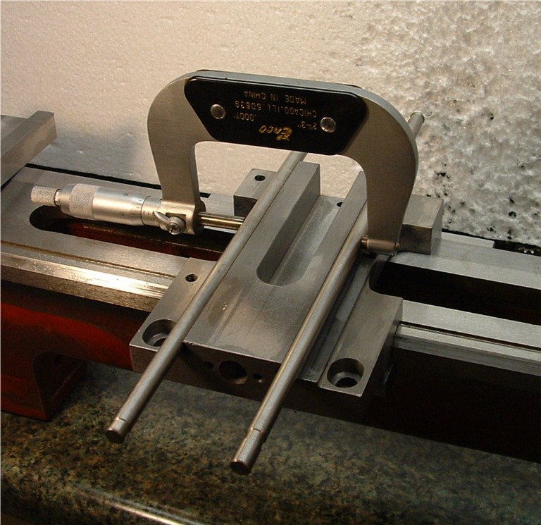 A liberal spray of
WD-40 and a bit of 80 grit was then smeared on three faces, two horizontal and
the non-gib
angled face then gib adjusted to a medium drag and given about two dozen strokes. As the grit breaks down the gib is tightened and repeated until the majority of the milling machine marks were removed from the horizontal registers. Then satisfied it is disassembled, cleaned with brake cleaner and clean shop rags and repeated with 120 grit, then 220, then 320, then 400 and finally 500 grit. I should mention I guess that before this operation started a feeler gauge measurement between the upper flat of the saddle and the lower face of the cross slide was taken which measured a "loose" .015". I should also mention that between each grit change a four corner measurement was taken to assure straight and true. This was abandon after the third grit as no change was apparent. End feeler measurement came in at .011" so .003" removed to get her squared up. After the end of the 500 grit the entire assembly is dismantled and rigorously cleaned with brake cleaner and rags until a white towel comes up clean. Then wiped down with acetone, reassembled and oiled and the slide worked back a forth while adjusting the gib for fit. When you do this you will find that even though you thought you had it spotless the oil will pull more grit from the surfaces. Continue to oil, work it until the oil darkens, clean, and repeat until the oil remains clean. About a half dozen cleanings are required. Unlike the saddle,
wet/dry paper isn't going to work here. I
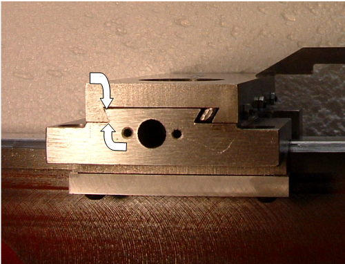
used dry lapping grits and WD-40 for a carry oil. Brake cleaner and shop towels for clean up. Lay out die to keep track of progress, and a lot of measurement as I proceeded. However before starting the base of the cross slide was blued and check for flat on the lapping plate on 2000 grit wet/dry. Yes, it was bowed and worked down flat with courser grades of paper and WD-40 until a few swipes across the plate on the 2000 paper would remove all bluing. About a thou was needed to straighten it out. Once satisfied that it was not only flat but all four corners measured the same thickness the gib, which was already lapped and pirated from the small lathe, was mounted to the saddle loosely. 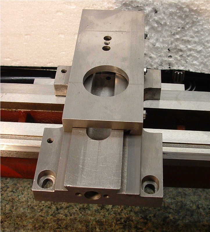 This photo is about
half way through the clean and oil stage.
You can still see a bit of gray on the right hand track. 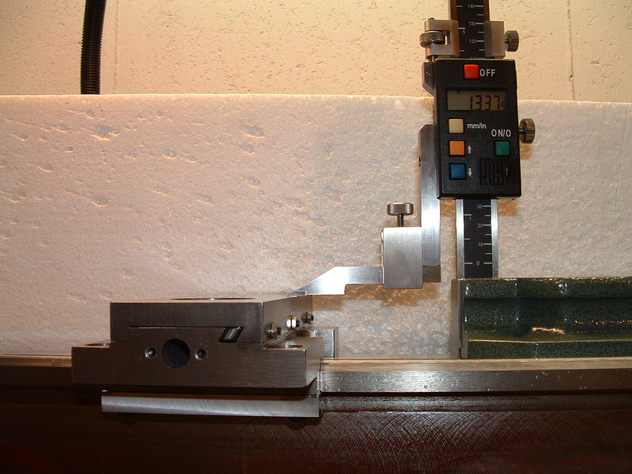 Final four corner
check being made with slide
centered on the saddle. All four measured -0 / + .0005 of 1.337" (33.97 mm) ISO-68 Way Oil was used here as was on the saddle. That may change latter. Note: The new height
gauge? Less than a hundred bucks at Harbor Freight. The Starrett manual
vernier is likely
more accurate but much harder to read with these old eyes. Quite affordable and has paid for itself already. This operation took three evenings to complete. Two hours a night and a fair amount yet to go. You may have noted that the gib side angled face hasn't been touched yet and there is a reason for that, two actually. The first is that as I had a perfectly parallel set of doves I didn't wish to chance skewing them so one, for now, was left untouched to reference the other three to. The second reason is a much bigger problem and I'll need some time to sort this one out. The original gib from the short machine had been plate lapped just like the instructions say on the Mini-Lathe site. I figured no need to reinvent that wheel. But I had never been totally happy with it as no matter how careful I was I could never get a good match of gib the saddle. It always favored one side or the other, top or bottom. Just today I figured out why this is and there are two parts to the problem. First the dimples for the adjustment screws aren't dimples at all but three drilled holes the length of the dog point and the same diameter of same. ANY lapping carried out the does not leave the centerline of these holes at dead right angles to the mating face puts a bind on things and rocks the gib, or twist it or bends it depending upon the exact adjustment. It doesn't need any help as it is machined bent, twisted and bowed. The second is that the gib is not the same height, top to bottom, as the dove slot height and the reason I guess that the adjusters aren't just dimples but the drilled holes must serve as guides as well! Hum, that isn't going to work very well. It is not an insignificant amount at .040". It is also narrower than the slot by just about .030". Thus under adjustment they rock about the adjuster tips and flop either up on down creating the single line pattern I had observed upon disassembly. Placing a light behind the slide I observed at least a 10 degree yaw and no matter how I tried or how tight I made them. I could not get full face contact. I had a spare new factory gib on hand. I took it and the original to the surface grinder. New factory gibs have no registers for the gib grubs. The original looked flat and looked straight but grinders tell no lies. A few passes and I junked it. I checked the new one on a surface plate to check for gross dimensional problems and found none so to the grinding table it went. It cleaned up pretty well and not more than .005" had to be taken in any plane to get her squared up, flat and parallel. A quick chamfer on the ends and a diamond stone to knock of the burrs and we were looking good. I set the gib up in the slide assembly with a .035" shim below it and used a transfer punch to mark the locations of the adjusters then spot drilled them just to a dimple large enough to capture the dog pointed ends. Pulled the shim and tried an adjustment. Hum same problem even though this gib was a bit larger and square six ways to Sunday. Okay, I had some .035" X .250 260 brass stock long enough. I made a permanent shim a bit longer than the gib and broke the ends up so that the ends captured the gib then profiled the ends to the gib shape to prevent fouling the dove as it moves. This worked quite well and a blue test showed good contact even though this side was yet to be lapped in. I used some of my adhesive backed sandpaper on the face of the gib and got it much closer and contacting completely from top to bottom but I still have high spots on both ends that needs some work but were going to put that off for the moment. These factory gibs are JUNK. Gummy and without much memory. You will bend it slightly during adjustment and it will remain bent thus making all your hard lapping work for not. Their hard to grind and even harder to de burr effectively and further more just not the right size to be stable. The brass horseshoe shim is a band-aid until I can make a proper gib for it. Likely A-2 or maybe bearing bronze but certainly not brass. I am a bit surprised how well the shim works though and the idea may make a good low budget band-aid for others. 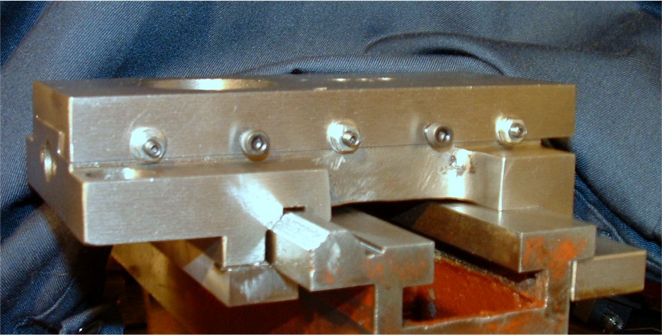 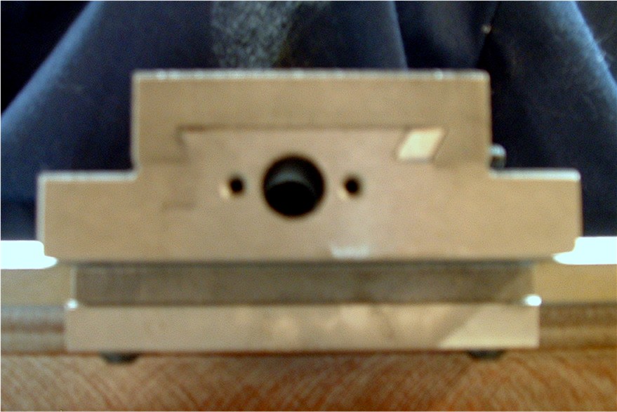 06/30/2007
Look at the photo on the right above and compare to the photo at the top of the page. We're looking at the gib. This is full dimension gib of A2 tool steel I made on the Bridgeport. Full height, full width and full length. It completely fills the slot. The upper photo shows the factory gib made of some soft ferrous material, bent, twisted, bowed and not nearly large enough to fill the slot. And this was a replacement gib which was allot better than that which came with the machine. A rough blank of A2 was selected from the scrap box and roughed into a rectangle approximately 7 inches long, .250" hight and about .450 wide. You need the extra width to accommodate the 60 degree angles. After squaring and cutting in the angles, which were left fat by about .040" in height and width, the hight was surface ground in to just less than full height of the slide. There is a slight step from the lapping that demands this step. I hang on to the piece with a magnetic chuck. Then the width is ground in to "just" slide in, maybe .0005". One you can get it in the slot the end is squared and fit for length and both ends chamfered 45 degrees, .040" wide. The center and two end original gib adjusting screws and marked with a transfer punch for location. Back in the mill and dimples drilled with a short center drill whose point was just a few thou larger than the dog points. Nice fit! Next the slide proper finds it's way to the mill. I used a pin gauge mounted in a drill chuck to find the X and Y locations and distances between existing grubs. The distanced halved and the pin gauge traded for a 39 letter bit and holed drilled completely though. Then the bit traded for a 60 degree center point, a Tee handle and 4 mm X 0.70 tap set loosely in place and the center point brought to bear lightly on the end of the tap. This keeps in alignment. Tap and hole oiled well light pressure, just enough to maintain contact is applied with the tap turned by the Tee handle with the other hand. Frequent chip breaking, blowing out the flutes and patiences. Both holes taped they were relieved with a 30 degree (60 included) tool fit in the chuck. This prevents pulling up the first thread. The two Allen head cap screws had a corresponding 60 degree angle ground on the end of the thread so no dimple was fit to the gib for this. Also maintains a slight upward pressure on the gib. These extra screws made a world of difference. Not only to they lend extra support, which is hardly needed with a gib this stiff, but make nice slide locks as well. All in all this came out much nicer than I had envisioned. This slide can be ran of the saddle 1-3/4" in either direction before a DTI picks up the faintest indication of displacement of the slide. As it is a 6" slide that is 58.3% travel of rock solid movement. Almost double the factory capability. I think the head stock will be next. Before I invest a world more work on this project we need to know what the cut in is of the slide. That is to say will it cut flat to a hair concave so a head stock with quill and a jig will need fit up next. 
August 28,
2007
Awhile since the last update eh? Won't even try to explain it. Now that the saddle is fitted I need to know pretty soon how square it will be to the spindle. To do that I need a spindle and need it mounted in it's final form. I've decided to emulate the Southbend 10K spindle snout to broaden the options and simplify my tooling requirements. Below is a before and after photo of that project. I had some other
goals in mind as well. As
we will be fitting taper bearings to this I wanted to add proper seals. I've chosen an SKF # 18536, which will require re- manufacture of both current dust covers to accommodate this modification. These are double lip seals 8 mm wide. I suppose some dimensions are in order here. Thread is a 1-1/2" X 8 TPI fit 2B and is .6875" in length or 5 1/2 threads. Pilot dimension is 1.509 (-0 + .003) X .1875" The seal area which you'll see in the next snap is 1.875" OD X 11 mm or what was left over of the original spindle flange. Thing about the seal
area is that it can't have any threading from the turning process. Actually this
area should
be ground to a 30 RMS finish. I didn't do this. Instead I finished .0015 over size, a hair more than the tool tip radius and hand polished it in to finial dimension. Guess I should say Ron, the machine operator. This was done on a HASS CNC turning center. Set-Tru chuck was used and the spindle indicated in to dead zero from the bearing register. I knew a Southbend was hiding in there :) 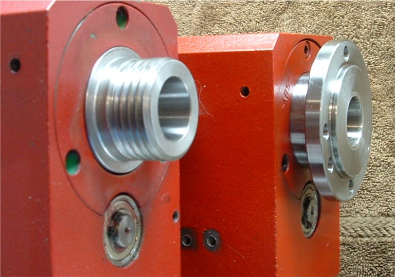 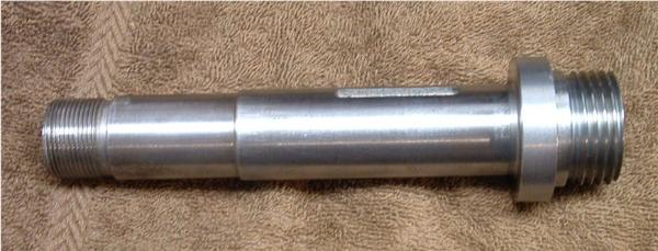 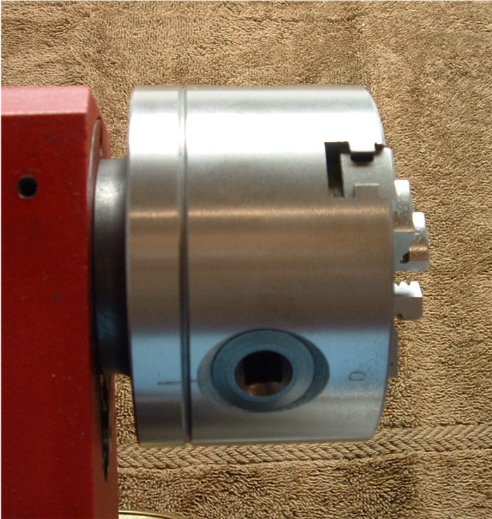 This is the Bison 4"
three jaw scroll chuck (from the products
page) mounted up. The result of this is, you will note, is that the "adaptor flange" now replaces the space of the original spindle flange which does a host of very important things. 1.) Shortens the length of the over hanging load. 2.) Reduces the weight of the over hanging load. 3.) Increases the chuck to tail center distance by more than the thickness of the adaptor. (I'll explain shortly) 4) Allows chuck changes in under 30 seconds 5.) Allows me to use chucks between machines, less tool holding (yes they repeat to under a thou between machines) 6.) Allows use of commercially produced adaptor flanges that can be made into a bunch of other tooling like face plates and catch plates or special fixtures at reasonable cost. 7.) Allows me to
move the work in the lathe to the mill or rotary table without loss of
reference if it needs to go
back to the lathe for a further operation. 8.) Commercial ER collet holders can now be direct fit or flush mount on made on machine adaptors. This also means I can get the saddle and tool to the back side of the work in a thread on ER for other operations without interference or worry of fouling it on the spindle flange. 9.) I can mount a 4" four jaw on a 5 or six inch back plate and make an in place and joint less indexing head! 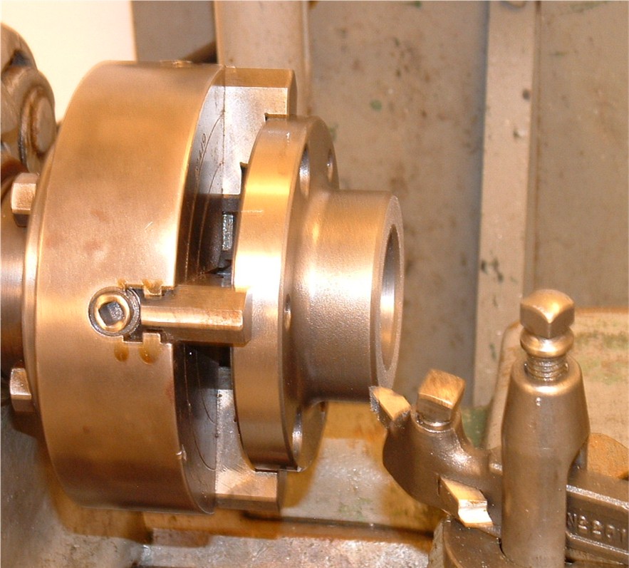 Now that
explanation. This is the adaptor plate of the chuck
unmounted from the chuck and indicated in a 5" four jaw on my SB 10K (which will also fit the Sieg :) Look at the picture above at the distance between the back of the flange and the front of the headstock. Not going to get any fingers in there are you? As adaptor plates of this thread size are made to fit all machines with this thread they accommodate the longest one thus over a half inch could be removed and in the end it set the face of the flange back further that the original. Not allot mind you but pennies make dollars. 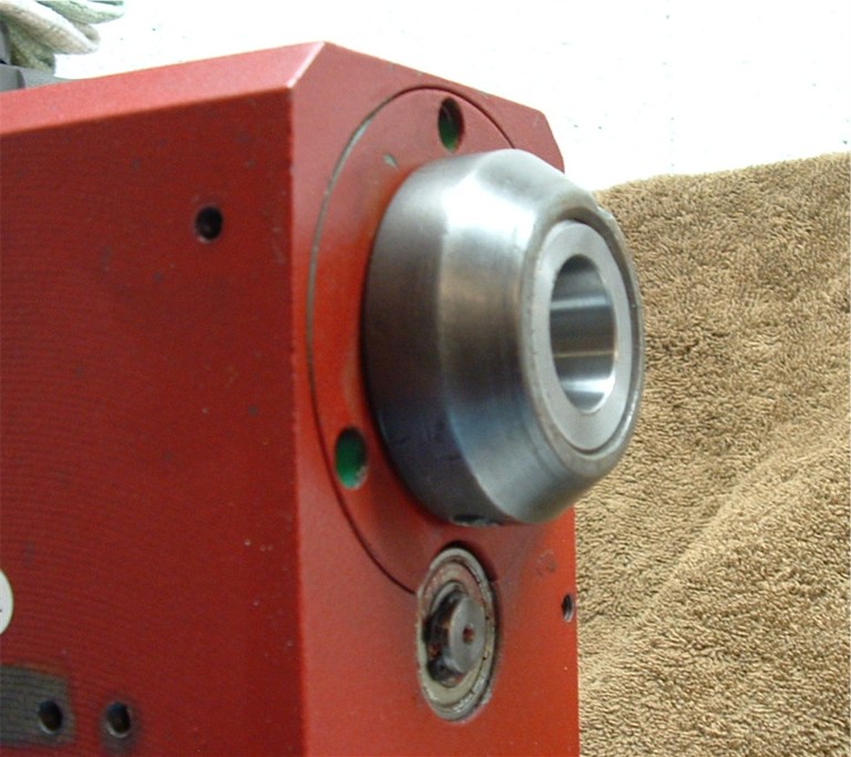 Spindle thread
protector straight off the SB 10K
for the 3C collet system. Now we have a 4" chuck in less thickness than the factory 3" chuck mounted in, on the shorter 10" head assembly on a 14" bed. Anymore length will come from the tail of the machine. This modification could also be done with in the Myford 7 platform for those across the pond or down under. Fitting the Tool Slide
11/20/2007 Finally, a few days vacation and I spent the first one working of the tool slide. Actually my third run at this. No photo's this time as it would be a repeat of the cross slide in every detail and photo's take up space. This is a multi part project. As per my usual custom part A was to make a decent gib. Now that I've done several of these it went much faster and with even better results. Someone suggested on my last gib that in the future I use drill bits or plug gauges to find the face width. Done, and is that easier than drawing and calculating it. Thanks who ever that was, great tip. It's also a great way to find irregularities in the dimensions of the slot width. I started with a piece of material that was much closer in finished dimension as well, another time saver. A 6" length of quarter thick by half wide ground unhardened A2. Having this it went to the surface grinder to finish to the face thickness, that is the thickness from adjuster to working face and to the larger of the two end dimensions which were .001" apart. Next to the mill where I set up a tool vise in the jaws of the milling vise and set with a sine bar to 30 degrees. Machined one side then flipped it over and brought the second side to the height spec required - .002". Cut to length, de-burr and test fit. Supper snug. In fact wouldn't travel the entire slide but expected that as there was a slight taper in the dove as the first measurement showed. Good enough thought to transfer punch the adjuster locations. Remove, set up in the mill again and spot drill the relief's for the adjusters. Took the lower half of the slide and gave the bottom a quick wipe on the lap plate just to assure no nicks. Laid it up on the surface plate and height gauge in the bottoms of the doves, both sides, both ends. Ouch! The gib side was .0015" taller than the off side but good end to end. Glad I left the gib short .002". Pair of Thomson rods in the doves and measured the cross difference, .0008" wider at the handle end which just confirmed what the gauge pins told me more accurately. A piece of sticky back 320 on the top section and a .010 shim on the off side (measured thickness of the paper) and in a few minutes of measure and wipe had both sides the same height within .0002". I'd made a 60 degree lap on the last gib job. Sticky back on it and worked to offending width problem at the point a bit of blue and touch up had identified as the high spot. Re-measure everything. Looked good. Clean, assemble and lube. Still a bit of stick at the one end and a bit of daylight in the off side gap. Hum. .0002" isn't close enough, but I knew that from previous work on the saddle and cross slides. A bit of 320 lap powder and light oil in a few minutes we were gold. Clean, lube and assemble again, adjust up the gib. Much better. Not perfect but very, very good. I'll work it more latter. Perfect has a way of finding imperfect. One of the first modifications I did to the lathe was to fabricate a double thrust ball bearing mount for the feed screw. It's pictured on the front page of my site. It's a matter of blind luck that when fabricating the bearing mount that I left the ID of the bearing bore a couple thou oversize of the bearing OD. Than allows a bit of float that came in handy when the lower slide dove height was lowered to match the off side. Rather be lucky than good any day, eh? Especially sense I used flat head screws and counter sinks thus the block height is not adjustable. Whew, dodged a bullet :) This block is square ten ways to Sunday. The imperfect part is the feed screw. All assembled and mounted the screw has a tight, loose rotation each half rotation when fully retracted the last quarter of it's length but fine for the last 3/4 of extension. One of two possible problems I see here. Either the thread axis is not concentric to the bearing axis or the screw has a bit of bow in it. Bowed I can fix, off axis is a scrap and remake. Never the less, I'll likely not do anything about it as from a functional standpoint it's fine. It requires no great effort, just noticeable. By default I am now committed to the .040 metric set up and good with that. Zero backlash due to feed screw to mount slop, .002" backlash due to thread to nut clearance, very livable. I mentioned at the beginning that this was my third run at this. The first got derailed when I found the doves of the original bottom half of the slide so far out of parallel as to be un-fixable. I bought a new lower from LMS to the JWE design. Ground in a factory gib and did a bit of light work which served the machine until it was dismantled for this project. That pretty much finishes the gibs on this machine, saddle, cross slide and tool slide. So what was the end result? Placing a DTI mounted on the bed and indicator tip on the tip of an indexable tool mounted in my A2Z QCTP and applying 10 lbs of downward pressure to the tool tip netted under .00015" total deflection with all slides centred. This test with my best adjustment previous to refinement netted about .005" deflection. Thats a 33 X improvement! As the gib adjusters are on closer centers than the cross slide was I'm electing for the time being not to add the additional adjusters nor lock screw. A minor item to fix if needed latter. I think this part of the goal accomplished! |
Looking for mini-mill help and how-tos? How about lathe help and how-tos?
We're prototyping a benchtop CNC vertical mill using the DigiSpeed-XL interface card for Mach, Dart Controls and KB Electronics KBIC/KBMM 90VDC motor controllers, 1.5HP treadmill motor from Surplus Center and a R8-spindle head from the X2 mini-mill - not to mention Gecko servo drives and an entirely closed-loop system. Come take a look!CNC 8x12 Lathe
Check out our newest developments like the CNC/DRO 8x12/8x14 lathe using Gecko drives, break-out board, NEMA 34 step motors, DRO and more!
SUPERX3.COM
Sieg X3 and Super X3 Grizzly G0463 Info
MDAHacks.com
T-Mobile MDA / Cingular 8125 / HTC Wizard Hacks, Tweaks, Tips, Tricks and More!
Metal Working FAQ.NET
Your source for metalworking and machining, tips, tricks, and more. Over 50 content wiki sites!